Common Mode Choke Tutorial

In this configuration normal mode current flows into the circuit through one of the windings. The differential mode signal component is v diff and the common mode signal component is v com.

Horizontal Big Current Toroidal Common Mode Choke 2 Cores

Horizontal Big Current Toroidal Common Mode Choke 2 Cores

Common Mode Chokes Signal Dc Power Lines Murata Digikey

Common Mode Chokes Signal Dc Power Lines Murata Digikey

We Fc Common Mode Power Line Choke Common Mode Chokes For

We Fc Common Mode Power Line Choke Common Mode Chokes For

In normal or differential mode single choke current travels on one line in one direction from the source to the load and in the opposite direction on the return line that completes the circuit.


We Fc Common Mode Power Line Choke Common Mode Chokes For

Common mode choke tutorial. Common mode chokes usually have two separate windings which are each put in series with each line conductor. Winding the 11 common mode choke duration. Ham radio the back yard vertical part 3.

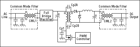
When using a current compensated choke to decrease common mode noise the interference pattern or the unwanted noise you want to have a high impedance at the unwanted frequencies to knock down that unwanted noise. The common mode chokes can be used in various industries such as industrial electronic and telecommunication applications such as ieee1394 lines for pcs panel link for lcd panels and countering common mode noise affecting signals in high speed lines. Parasitic capacitance that exists between the cable and gnd are shown as c p.

Simply put they are filters that act only on common modes. Common mode choke coils are noise filters that discriminate between signals and noise from the above mentioned common modes and differential modes or conduction modes. These two windings are wound on the same ferromagnetic core in a way that exploits the different path that power line current and cmn currents take in the circuit.

A common mode choke is where both line and neutral windings are wound on a single core. This type of choke is called a ferrite choke or ferrite bead. In common mode the noise current travels on both lines in the same direction.

A common mode choke includes a magnetic core and two windings making it a four terminal device. V 1 v 2. Pdf version a common mode choke is an electrical filter that blocks high frequency noise common to two or more data or power lines while allowing the desired dc or low frequency signal to pass.

The two windings have the same number of turns and are wound in opposite directions in a mirror configuration. Kevin loughin 14322 views. 21 differential mode signals for pure differential mode.

Vertical T50 Common Mode Choke Tutorial Pbt Base Pulse
Vertical T50 Common Mode Choke Tutorial Pbt Base Pulse

Can A Common Mode Choke Be Used At The Output Of An Smps

Can A Common Mode Choke Be Used At The Output Of An Smps

Common Mode Choke To Pass Emc Test Avr Freaks

Common Mode Choke To Pass Emc Test Avr Freaks

Vertical T50 Common Mode Choke Tutorial Pbt Base Pulse

Vertical T50 Common Mode Choke Tutorial Pbt Base Pulse

Control Engineering Achieve Emc Compatibility For

Control Engineering Achieve Emc Compatibility For

Electrical Noise Suppression And Common Mode Choke

Electrical Noise Suppression And Common Mode Choke

Toroidal Common Mode Choke On Sale Toroidal Common Mode

Toroidal Common Mode Choke On Sale Toroidal Common Mode

How To Use Common Mode Choke Inductors Differential Vs

How To Use Common Mode Choke Inductors Differential Vs

Basics Of Noise Countermeasures Lesson 6 Common Mode Choke

Basics Of Noise Countermeasures Lesson 6 Common Mode Choke

Common Mode Power Line Chokes Wurth Electronics Digikey

Common Mode Power Line Chokes Wurth Electronics Digikey

Common Mode Coax Noise Filter 500 Watts 1 8 60 Mhz

Common Mode Coax Noise Filter 500 Watts 1 8 60 Mhz

Choke Electronics Wikipedia

Choke Electronics Wikipedia

Comments

Popular posts from this blog

Electrolytic Capacitor Symbol In Proteus

It is then co simulated along with any analog and. And there are variable capacitors polarized or nonpolarized. F Quer September 2013 Electrical Component Basics The Capacitor Steemit Simple Fm Transmitter Circuit Based On Two Transistors These 100v33000uf proteus electrolytic capacitors are widely appreciated by our clients which are situated all round the nation. Electrolytic capacitor symbol in proteus . In this article we show the schematic symbols for capacitors. In detail the question is which properties of an electrolytic capacitor you want to model additionally. It acts as short circuit with ac and open circuit with dc. A non solid electrolyte covers the rough surface of the oxide layer serving in principle as the second electrode of the capacitor. There are polarized capacitors such as electrolytic capacitors. If its esr add a series ...

Common Mode Choke Low Pass Filter

Investigation Of Noise Conditions Murata Manufacturing Co Dual Function Chokes Address Differential Common Mode Common Mode Choke Design Marque Magnetics Hf Low Band Common Mode Choke Current Balun 3500w Design Techniques 3 Filters And Spds Without Graphics Basics Of Common Mode Noise Filters Industrial Devices Converter And Inverter Output Filtering Avnet Abacus Filtering Out Common Mode Noise With Monolithic Emi Filters Basics Of Common Mode Noise Filters Industrial Devices Emc Emi Filter Design With Rb Common Mode Chokes Conductor Conduction And Common Mode Murata Manufacturing Ham Radio Rfi Tv Interference Filter ...

Explain Shunt Capacitor

Providing Capacitive Reactive Compensation With Shunt Shunt Resistor Resistor Guide Shunt Capacitors And Their Applications Power Quality In Understanding Series Capacitors Power Quality In Filter Circuits Working Series Inductor Shunt Capacitor Rc Effect Of Series And Shunt Compensation On Voltage Stability Shunt Capacitive Compensation Shunt Inductive Compensation Capacitor Filter Using Half Wave And Full Wave Rectifiers Solved What Are The Voltage Regulating Devices Used In A Solved A 120 V 60 Hz Circuit That Is Protected By A 15 A E 042 Shunt Capacitor Bank Design And Protection 2 Pdh 6 2 Exercise 2 A Explain Why The T...