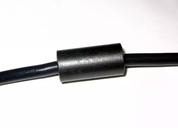
The name choke is used if an inductor is used for blocking or decoupling higher frequencies but is simply called an inductor if used in electronic filters or tuned circuits. They are able to generate magnetic fields when they carry current.

What Is An Inductor Coilcraft

Uxcell Axial Lead Color Ring Inductor 100uh 150uh 220uh

High Insolation Between Windings For Ee Type Inductor Choke Coil
An electric field set up because of the potential difference between the two conductors or we can say between the two plates.

Difference between inductor and choke coil. When as electric current is passed through a coil voltage is developed across the coil due to change in the magnetic field. The difference between capacitor and inductor are as follows. Choke coil an inductor used in a special application to impede the current in a circuit over a specified frequency range while allowing relatively free passage of the current at lower frequencies.
The main function of an inductor is used to store energy in a magnetic field. It is a functional name. When a current flows through this coil then temporarily stores the in the coil.
It consists of a wire generally twisted into a coil. Inductor a device consisting of one or more associated windings with or without a magnetic core for introducing inductance into an electric circuit. What is the difference between ac choke inductor and dc choke inductor in a working and design point of view.
Inductors are metal coils used in circuits. Due to these multiple layers and the insulation between them multi layer inductors have a comparatively high inductance level. An inductor also called a choke or reactor is a passive two terminal electrical component.
Ceramic core inductors a ceramic core inductor possess a dielectric ceramic core. Multi layer inductors this particular type of inductor consists of a layered coil wound multiple times around the core. Inductor is a type of coil which stores energy in the form of magnetic flux.
They are also able to induce magnetic fields in wires that are near them. A coil of wire acts as an inductor. It is made of an electrical conductor for example a wire normally wound into a coil.
Inductors that are used to help filter signals are called chokes. It is made of an electrical conductor for example a wire normally wound into a coil. An inductor or coil or choke is a two terminal device that is used to build various circuits.
It will have a very small resistance and a relatively large inductance. Power factor is effectively the resistance divided by the impedance made up of resistance and inductance so the larger the inductance relative to the resistance the lower the power factor will be. Chokes for even higher frequencies have non magnetic cores and low inductance.

Inductor And The Effects Of Inductance On An Inductor

What Is The Difference Between An Rf Choke And An Inductor

Choke Coil Manufacturers Choke Coil Suppliers

3 Ways To Measure Inductance Wikihow

Main Difference Between Capacitor And Inductor

Details About Siemens Components 1uh 1µh 6a Inductor Choke Coil Inductor Choke Coil Axial

China Choke Coil From Xi An Trading Company Shaanxi Shinhom

Hot Item Replace We 7448052303 Common Mode Choke Coil Inductors

Choke Electronics Wikipedia

550µh Inductor Choke Coil

Common Mode Choke Coilcraft

Choke Electronics Wikipedia
Comments
Post a Comment