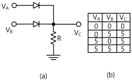
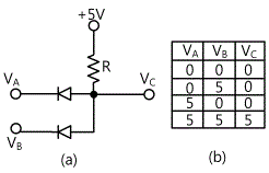
Logic circuits perform logical operations on the behalf of boolean logics. Nor diode transistor logic dtl gate.

Lessons In Electric Circuits Volume Iv Digital Chapter 3

Nand Gate Using Diode Circuit

Or And And Logic Gates Made With Diodes Electronics Area
Figure 3 49 shows the circuit diagram of a diode and gate.

Diode or logic circuit. It is seen that the diode anodes are connected to a 5 v supply v cc via resistor r 1. The two basic logic circuits are the and gate and the or gate. Or and and logic gates made with diodes.
Diode logic dl or diode resistor logic drl is the construction of boolean logic gates from diodesdiode logic was used extensively in the construction of early computers where semiconductor diodes could replace bulky and costly active vacuum tube elements. If we need a or gate we can use a 4071 or cmos ic or a ttl 7432 or ic. Figure 3a gives the circuit symbol and boolean expression for nor gate while figure 1b gives the two input truth table.
The most common use for diode logic is in diodetransistor logic dtl integrated circuits that in addition to diodes include. In this project we will show how to build an or gate circuit with diodes. Diode logic uses the fact that diodes conduct only in one direction.
An or gate is a logic circuit that turns on an output if one of the inputs is high or a logic state of 1. Logic circuits are primarily implemented electronically using semiconductor diodes or transistors but it can be constructed using different basic logic gates which are implemented by electromagnetic relays fluidics molecules optics or even mechanical elements. A diode logic circuits produces an output voltage which is either high or low depending upon the levels of several input voltages.
If we need a and gate we can use a 4081 and cmos ic or a ttl 7408 and ic but sometimes it is easier to use diodes. An or gate immediately followed by a not gate constitutes the or not or nor gate. They behave like switches.
Some logic gates can be produced with just diodes and resistors called diode resistor logic or drl. Or gate using diode. How to build a diode or gate circuit.

Experiment 1 Diode Logic Circuit Part13fundamental Logic

Digital Logic Or Gate

What Is The Basic Idea Of The Input Logical Part Of

Diode Switching Circuit

Negative Inputs For Diode Transistor Logic Electrical

Lessons In Electric Circuits Volume Iv Digital Chapter 3

Logic Families Digital Electronics

Digital Logic Gate Tutorial Basic Logic Gates

Experiment 1 Diode Logic Circuit Part13fundamental Logic

Diode Switching Circuits Diodes And Rectifiers

Digital Electronics Logic Gates Basics Tutorial Circuit

What Is The Basic Idea Of The Input Logical Part Of
Comments
Post a Comment