Diode With Gate

1 graphical method 2 diode approximation. The 1n400x diodes are an easy type to find and very cheap so any one from that family can be used.

Determine The I And V Of A Logic Gate Electrical
Determine The I And V Of A Logic Gate Electrical

Diodes The Switch You Never Knew You Had Hackaday

Diodes The Switch You Never Knew You Had Hackaday

Diode Logic

Diode Logic

If we need a and gate we can use a 4081 and cmos ic or a ttl 7408 and ic but sometimes it is easier to use diodes.


Diode Logic

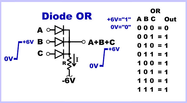
Diode with gate. Some logic gates can be produced with just diodes and resistors called diode resistor logic or drl. A diode or gate with positive logic truth table the image to the right shows a diode or circuit. All diodes have inputs on their anodes and their cathodes are connected together to drive the output.

In this video different methods for solving the diode circuits have been discussed. Since we are building a 3 input or gate we will need 3 diodes. So in this post you will learn how to make an and gate using diodes on breadboard.

Diode logic uses the fact that diodes conduct only in one direction. Diode and and or gates can be designed and constructed using discrete components. The diodes really can be any type.

You must be familiar with an and gate its truth table logic symbol and its working. Sometimes it is convenient to fashion a single logic gate from a few diodes. But do you know you can build your own and gate on breadboard.

There are two methods for solving analyzing the diode circuits. Diodes can perform digital logic functions. Or and and logic gates made with diodes if we need a or gate we can use a 4071 or cmos ic or a ttl 7432 or ic.

An and gate is shown in the figure above. The amount of diodes you need are proportional to the number of inputs you want for the or gate. Diode logic was used in early digital computers.

The diode symbol is an arrow showing the forward low impedance direction of current flow. It only finds limited application today. We use a 10kw as a pull up resistor.

However integrated circuit ic packages are available containing many diode logic circuits already fabricated in the form of one or more gates.

Nor Gate Using Diodes And Transistor On Breadboard

Nor Gate Using Diodes And Transistor On Breadboard

Diode And Gate For Positive And Negative Logic And Gate

Diode And Gate For Positive And Negative Logic And Gate

How To Solve A Simple Diode Gate Question From Sedra And

How To Solve A Simple Diode Gate Question From Sedra And

4 Bi Directional Diode Sampling Gate Operation Gain Vcmin And Vnmin Jntu Pdc

4 Bi Directional Diode Sampling Gate Operation Gain Vcmin And Vnmin Jntu Pdc

Diode Logic Wikipedia

Diode Logic Wikipedia

Logic Gates

Logic Gates

Why Put A Diode Parallel To A Resistor Page 1

Why Put A Diode Parallel To A Resistor Page 1

Or Gate Using Diodes Everything Explained

Or Gate Using Diodes Everything Explained

Tps28225 Reverse Diode For Gate Drive Power Management

Tps28225 Reverse Diode For Gate Drive Power Management

Diode Clamp Ic Technology

Diode Clamp Ic Technology

Diode Logic Gates

Diode Logic Gates

And Gate Using Diodes Everything Explained

And Gate Using Diodes Everything Explained

Comments

Popular posts from this blog

Electrolytic Capacitor Symbol In Proteus

It is then co simulated along with any analog and. And there are variable capacitors polarized or nonpolarized. F Quer September 2013 Electrical Component Basics The Capacitor Steemit Simple Fm Transmitter Circuit Based On Two Transistors These 100v33000uf proteus electrolytic capacitors are widely appreciated by our clients which are situated all round the nation. Electrolytic capacitor symbol in proteus . In this article we show the schematic symbols for capacitors. In detail the question is which properties of an electrolytic capacitor you want to model additionally. It acts as short circuit with ac and open circuit with dc. A non solid electrolyte covers the rough surface of the oxide layer serving in principle as the second electrode of the capacitor. There are polarized capacitors such as electrolytic capacitors. If its esr add a series ...

Common Mode Choke Low Pass Filter

Investigation Of Noise Conditions Murata Manufacturing Co Dual Function Chokes Address Differential Common Mode Common Mode Choke Design Marque Magnetics Hf Low Band Common Mode Choke Current Balun 3500w Design Techniques 3 Filters And Spds Without Graphics Basics Of Common Mode Noise Filters Industrial Devices Converter And Inverter Output Filtering Avnet Abacus Filtering Out Common Mode Noise With Monolithic Emi Filters Basics Of Common Mode Noise Filters Industrial Devices Emc Emi Filter Design With Rb Common Mode Chokes Conductor Conduction And Common Mode Murata Manufacturing Ham Radio Rfi Tv Interference Filter ...

Explain Shunt Capacitor

Providing Capacitive Reactive Compensation With Shunt Shunt Resistor Resistor Guide Shunt Capacitors And Their Applications Power Quality In Understanding Series Capacitors Power Quality In Filter Circuits Working Series Inductor Shunt Capacitor Rc Effect Of Series And Shunt Compensation On Voltage Stability Shunt Capacitive Compensation Shunt Inductive Compensation Capacitor Filter Using Half Wave And Full Wave Rectifiers Solved What Are The Voltage Regulating Devices Used In A Solved A 120 V 60 Hz Circuit That Is Protected By A 15 A E 042 Shunt Capacitor Bank Design And Protection 2 Pdh 6 2 Exercise 2 A Explain Why The T...