Esp8266 Gpio Pull Up Resistor

A lower value resistor will pull the pin up harder making it more. When i do the pull up manually with a resistor my wiring works perfectly but when i add an internal pull up using the following line in my arduino ide code it does not work properly.

Esp 12e Vs Esp 12s Deep Sleep Wake Up Pulse Everything

Esp 12e Vs Esp 12s Deep Sleep Wake Up Pulse Everything

Esp8266 Arduino Digital Io Circuits4you Com
Esp8266 Arduino Digital Io Circuits4you Com

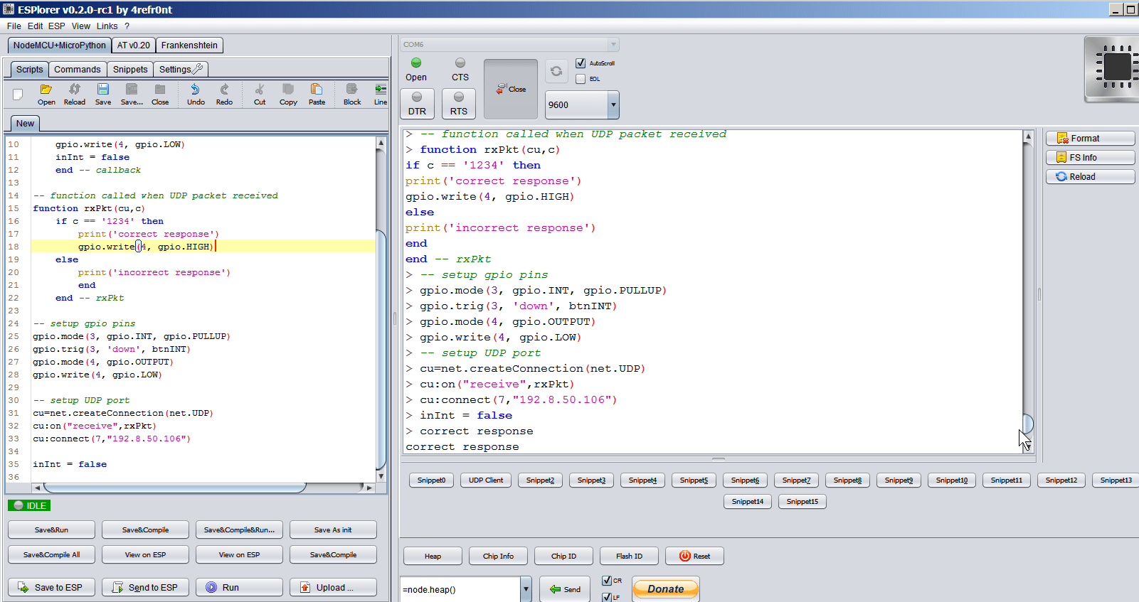
Esp8266 Reading Writing Gpio And Transmitting Receiving Udp

Esp8266 Reading Writing Gpio And Transmitting Receiving Udp

The esp8266 has a single analog input with an input range of 0 10v.


Esp8266 Reading Writing Gpio And Transmitting Receiving Udp

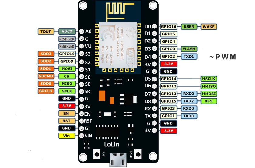
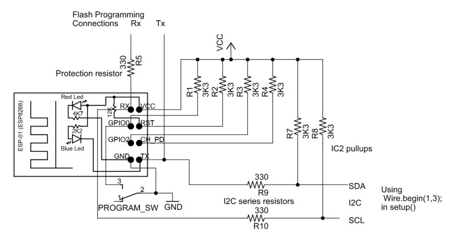
Esp8266 gpio pull up resistor. For gpio0 and gpio2 an external relay must be connected between vcc and the pin so that it does not interfere with the action of the pull up resistor. Gpio16 has a built in pull down resistor. Would it be okay for a long shot.

Im using 47kohm resistor as pullups for gpios 20216 chpd and reset and also 47kohm pulldown for gpio 15. Unlike most atmel chips arduino the esp8266 doesnt support hardware pwm however software pwm is supported on all digital pins. Resistor pull ups for esp8266.

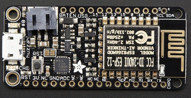
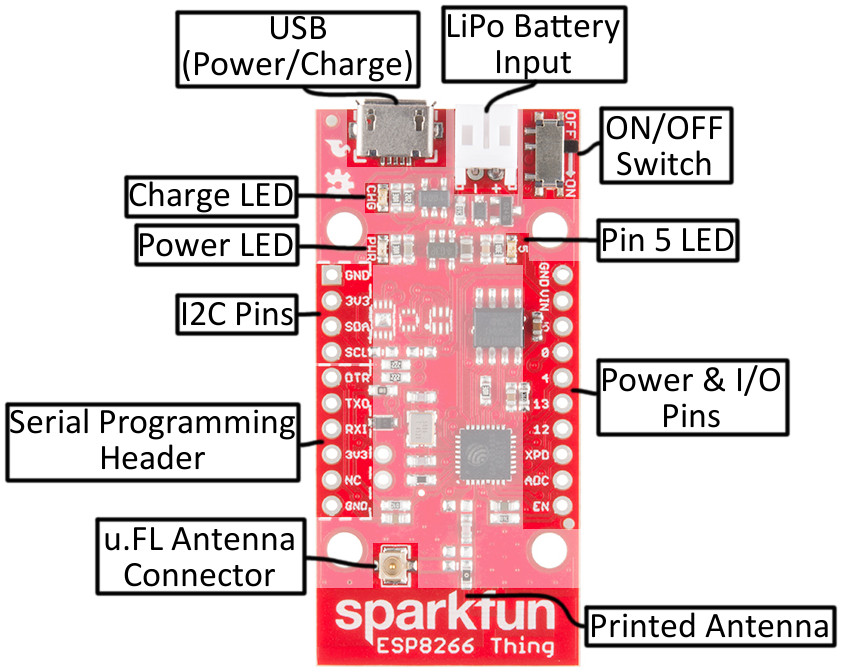
Should i use 10kohm instead of 47kohm. Conversely an external relay connected to gpio15 must be connected between gnd and the pin so that is does not interfere with the action of the pull down resistor. Below is the descriptions of gpio that you can refer to.

Dear bugless the value of internal pull up resistor is between 30kohm and 100kohm. The esp8266 boots and works fine. I am working on the adafruit feather huzzah esp8266 and i would like to add an internal pull up to a push button.

The default pwm range is 10 bits at 1khz but this can be changed up to 14 bit at 1khz.
Esp8266 Free Gpios For Relay Switching Electrical
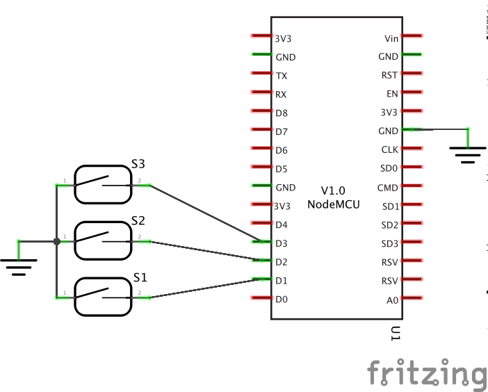
Esp8266 Free Gpios For Relay Switching Electrical

Github Patrickeasters Nodemcu Sensor Mqtt Nodemcu Code To

Github Patrickeasters Nodemcu Sensor Mqtt Nodemcu Code To

Esp8266 Relay Yet Another Post
Esp8266 Relay Yet Another Post

Esp8266 01 Pin Magic How To Use The Esp8266 01 Pins

Esp8266 01 Pin Magic How To Use The Esp8266 01 Pins

Esp8266 Gpio Pins Info Restrictions And Features Faq

Esp8266 Gpio Pins Info Restrictions And Features Faq

Esp8266 Gpio On Deep Sleep And Reset
Esp8266 Gpio On Deep Sleep And Reset

Quick Reference For The Esp8266 Micropython 1 12 Documentation

Quick Reference For The Esp8266 Micropython 1 12 Documentation

Wake Esp8266 By Input Signals During Deep Sleep The Same Way

Wake Esp8266 By Input Signals During Deep Sleep The Same Way

Mcu And Pull Up Pull Down Resistors Lukasz Podkalicki

Mcu And Pull Up Pull Down Resistors Lukasz Podkalicki

Esp01 Gpio2 Low At Boot Let S Control It

Esp01 Gpio2 Low At Boot Let S Control It

Esp8266 Gpio Measured Pin Behaviour On Deep Sleep Reset
Esp8266 Gpio Measured Pin Behaviour On Deep Sleep Reset

Esp8266 Thing Hookup Guide Learn Sparkfun Com

Esp8266 Thing Hookup Guide Learn Sparkfun Com

Comments

Popular posts from this blog

Electrolytic Capacitor Symbol In Proteus

It is then co simulated along with any analog and. And there are variable capacitors polarized or nonpolarized. F Quer September 2013 Electrical Component Basics The Capacitor Steemit Simple Fm Transmitter Circuit Based On Two Transistors These 100v33000uf proteus electrolytic capacitors are widely appreciated by our clients which are situated all round the nation. Electrolytic capacitor symbol in proteus . In this article we show the schematic symbols for capacitors. In detail the question is which properties of an electrolytic capacitor you want to model additionally. It acts as short circuit with ac and open circuit with dc. A non solid electrolyte covers the rough surface of the oxide layer serving in principle as the second electrode of the capacitor. There are polarized capacitors such as electrolytic capacitors. If its esr add a series

Explain Shunt Capacitor

Providing Capacitive Reactive Compensation With Shunt Shunt Resistor Resistor Guide Shunt Capacitors And Their Applications Power Quality In Understanding Series Capacitors Power Quality In Filter Circuits Working Series Inductor Shunt Capacitor Rc Effect Of Series And Shunt Compensation On Voltage Stability Shunt Capacitive Compensation Shunt Inductive Compensation Capacitor Filter Using Half Wave And Full Wave Rectifiers Solved What Are The Voltage Regulating Devices Used In A Solved A 120 V 60 Hz Circuit That Is Protected By A 15 A E 042 Shunt Capacitor Bank Design And Protection 2 Pdh 6 2 Exercise 2 A Explain Why The T

Draw The Diode Equivalent Circuit

Further it is open in a reverse biasing condition. The arrowhead on the symbol still points in the conventional direction of forward current when the device is forward biased. Diode Applications Half Wave Rectifier And Equivalent A Schematic Diagram Of Gunn Diode B Parallel Equivalent Two Diode Equivalent Circuit Model Of A Two Junction Solar Access resistances in vertical devices. Draw the diode equivalent circuit . Ideal diode in circuit. The output across the diode will be constant. The circuit symbol for a zener diodes characteristics in fig. It is because the value of reverse resistance is so high r r 100 mw that is considered to be an infinite for all practical purposes. The general representation for a practical diode under dc operating conditions is shown below. It is driven by a current source. As we know if the voltage